Component 2
2.4 Boolean Logic
Logic diagrams
As part of the course, you will need to recognise the three logic symbols opposite. There is no need to memorise any others.
A simple way to remember is that the AND gate looks a little like the letter 'D' which is the last letter of AND.
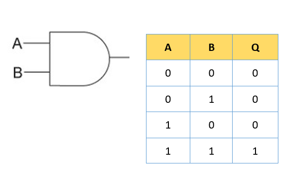
With an AND gate, for the output to be on, both input A AND input B must be on.
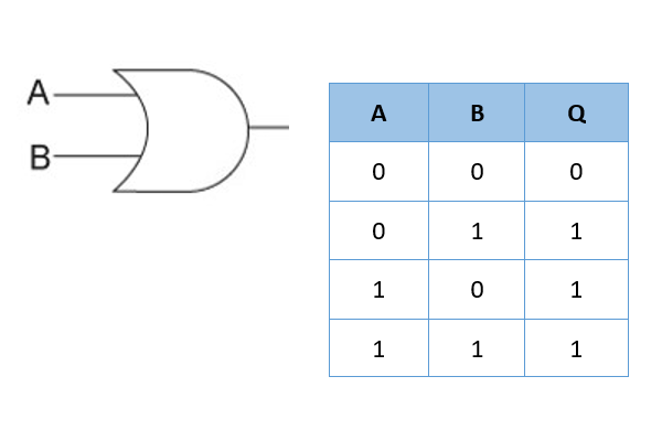
With an OR gate, for the output to be on, either input A OR input B must be on.
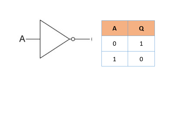
With a NOT gate, the output is always the opposite of the input. The output is NOT what the input is.
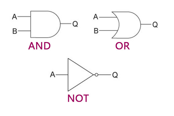
In addition to the diagrams, you also need to know the technical names and written symbols that can be used.
| Gate | Technical Name | Symbol |
|---|---|---|
| AND | Conjunction | ∧ |
| OR | Disjunction | ∨ |
| NOT | Negation | ¬ |
Truth tables
When creating a truth table, the first step is to fill in the table with every possible combination of the inputs. Each one could be a 1 or a 0.
AND gate truth table
OR gate truth table
NOT gate truth table
Combining gates
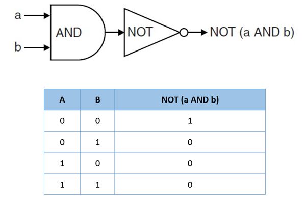
Gates with simple inputs
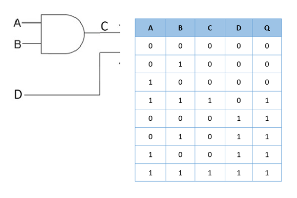
What you will need
Ensure you fully understand how each of the gates works. You will need to be able to construct truth tables for at least two gates together and it could potentially have other inputs as well.
Using Boolean logic to solve problems
You could be asked to create a Boolean expression from a given problem. You will need to think about the logic symbols and how they would combine for the given situation. Here is an example:
A vending machine allows a user to enter a product number (P). They must then enter a valid payment card (V). Only if the product number is valid and the payment card has available funds will the machine vend the product (O).
For this problem, we can say that:
O ≡ P AND V
